Find changed regions between frames
Compare two frames, suppress noise, clean the difference mask and draw connected changed regions.
The pipeline
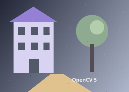
The unchanged source image. All steps use this same example.
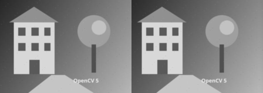
Both grayscale frames receive the same Gaussian blur before comparison. The second frame is on the right.
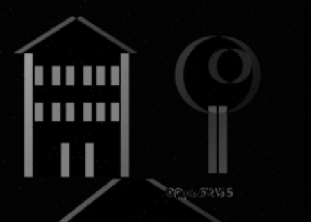
Differences after smoothing; unchanged areas are dark.

White marks pixels that pass the difference cutoff, before gaps are closed or small regions are discarded.

Morphological closing joins nearby differences before component filtering.
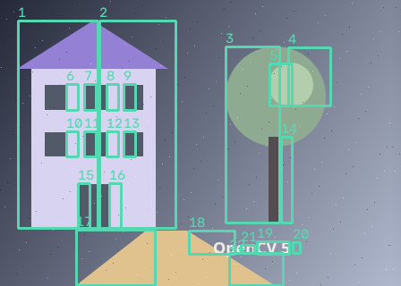
22 regions retained from 24 foreground components.
Suppress image noise
Explore the algorithm →GaussianBlurGaussian smoothing reduces isolated pixel differences.
- Receives
- Two equally sized grayscale frames.
- Passes to the next step
- Two smoothed frames on the same coordinate grid.
Why this step? Small sensor fluctuations and subpixel changes would create many isolated differences. Applying the same 5×5 Gaussian blur to both images suppresses some of that variation before subtraction, so thresholding is less sensitive to individual noisy pixels.
Threshold frame differences
Explore the algorithm →absdiffthresholdAbsolute grayscale differences become a binary mask.
- Receives
- The smoothed grayscale frames.
- Passes to the next step
- An 8-bit binary changed-pixel mask, plus an inspectable difference image.
Why this step? Absolute difference measures the magnitude of change without cancelling brightening against darkening. Thresholding converts that continuous evidence into a decision mask: white means the change exceeds your chosen intensity threshold.
Group changed pixels
Explore the algorithm →morphologyExMORPH_CLOSEconnectedComponentsWithStatsMorphological closing and component area filtering produce region boxes.
- Receives
- The changed-pixel mask.
- Produces
- Boxes and component IDs for changed regions large enough to retain.
Why this step? Closing joins small gaps within changed regions. Connected components assign a label to each contiguous region and compute its area and bounds. Filtering by area removes remaining tiny regions before drawing boxes.
Actual OpenCV 5.0.0 results on the illustrated sample, using the lab’s default algorithm settings. Masks, overlays and normalized fields are labelled previews; the data contracts above describe what the algorithms really exchange. Try this chain with your images ↓
Why this chain works
For aligned views, a pixel that changes enough is evidence of a changed region. The chain first suppresses small fluctuations, then turns differences into a mask, and finally turns that mask into objects you can count or box.
- 01
Suppress image noise
GaussianBlurSmall sensor fluctuations and subpixel changes would create many isolated differences. Applying the same 5×5 Gaussian blur to both images suppresses some of that variation before subtraction, so thresholding is less sensitive to individual noisy pixels.
- Receives
- Two equally sized grayscale frames.
- Passes on
- Two smoothed frames on the same coordinate grid.
- 02
Threshold frame differences
absdiffthresholdAbsolute difference measures the magnitude of change without cancelling brightening against darkening. Thresholding converts that continuous evidence into a decision mask: white means the change exceeds your chosen intensity threshold.
- Receives
- The smoothed grayscale frames.
- Passes on
- An 8-bit binary changed-pixel mask, plus an inspectable difference image.
- 03
Group changed pixels
morphologyExMORPH_CLOSEconnectedComponentsWithStatsClosing joins small gaps within changed regions. Connected components assign a label to each contiguous region and compute its area and bounds. Filtering by area removes remaining tiny regions before drawing boxes.
- Receives
- The changed-pixel mask.
- Passes on
- Boxes and component IDs for changed regions large enough to retain.
Tune and diagnose
Choose the parameters
Raise the difference threshold to ignore smaller intensity changes. Increase the cleanup kernel only enough to reconnect fragmented regions; large kernels merge nearby objects. Minimum area is measured after preprocessing and mask cleanup.
Read the result
If most of the scene becomes white, inspect camera movement or lighting changes first. Align the images before this chain when the camera moves. A moving object can create two changed regions, where it was and where it is now; this recipe does not estimate a motion vector.
Try it with your images
Choose an input image and a second image. Without uploads, the lab uses a labelled synthetic pair. Run the recipe, then use the stage buttons to inspect intermediate results without rerunning it.
Experiment at pixel level
Compare two frames, suppress noise, clean the difference mask and draw connected changed regions.
The engine loads on your first run. Your images stay in this browser.
Scroll over either image to zoom at the pointer. Use the scrollbars to pan both views over the same relative area. Zoom is relative to the input; pixel coordinates belong to each image. Warps can change scene correspondence.
Pixel inspector RGBA · native values · matched scale · 9 × 9 output pixels
Select a pixel
Select a pixel
Assumptions and limits
Camera movement and lighting changes also appear as motion. Use aligned frames for object-motion analysis.
TypeScript core chain
Initialize the shared engine once with await initOpenCV(), then use these named imports. In a bundled browser app, pass the WASM URL as shown in the quickstart. image is an 8-bit BGR Mat from that same engine; paired recipes receive an equally sized nextImage. Region recipes use an in-bounds pixel rect. Read outputs before the using scope ends. See matrix ownership.
import {
  COLOR_BGR2GRAY,
  GaussianBlur,
  MORPH_CLOSE,
  MORPH_ELLIPSE,
  Mat,
  THRESH_BINARY,
  absdiff,
  connectedComponentsWithStats,
  cvtColor,
  getStructuringElement,
  morphologyEx,
  threshold
} from '@banou/opencv-wasm'

// The engine is already initialized; image is an 8-bit BGR Mat.
// nextImage is the equally sized second frame from the same engine.
// "using" releases native handles at scope exit; inspect or copy outputs before then.

// 1. Allocate grayscale frames, an intensity-difference image and a binary mask.
using a = new Mat(), b = new Mat(), difference = new Mat(), mask = new Mat()
// Represent the first frame as brightness instead of three colour channels.
cvtColor(image, a, COLOR_BGR2GRAY)
// Use the same representation for the second frame; they must already align.
cvtColor(nextImage, b, COLOR_BGR2GRAY)
// Smooth the first frame with a 5x5 kernel and sigma 1 pixel to suppress small noise.
GaussianBlur(a, a, { width: 5, height: 5 }, 1)
// Apply the identical smoothing to the second frame before comparing them.
GaussianBlur(b, b, { width: 5, height: 5 }, 1)
// 2. Measure absolute brightness change, so brightening and darkening both count.
absdiff(a, b, difference)
// Changes greater than 25 intensity levels become 255 (white); others become 0.
// This makes a decision mask from continuous difference evidence.
threshold(difference, mask, 25, 255, THRESH_BINARY)
// Choose a small elliptical 3x3 neighbourhood for cleaning that mask.
using kernel = getStructuringElement(MORPH_ELLIPSE, { width: 3, height: 3 })
// Closing dilates then erodes, joining small gaps within changed regions.
morphologyEx(mask, mask, MORPH_CLOSE, kernel)
// 3. Prepare one label per pixel, per-region statistics, and x,y centroids.
using labels = new Mat(), stats = new Mat(), centres = new Mat()
// Group connected white pixels. stats rows contain left, top, width, height, area;
// row/label 0 is background. The full lab filters small areas and draws region boxes.
connectedComponentsWithStats(mask, labels, stats, centres)
The snippets isolate the core operations. The complete runnable recipes also include validation, filtering, overlays, intermediate previews and resource cleanup.